System RC1
![]()
Overview
![]()
Hardware
![]()
RC1 SCADA
![]()
Implementation
![]()
Reference
![]()
Overview
System RC1 is a sophisticated microcontroller based system, utilizing the latest technology, specifically designed for the needs of electricity boards. It was designed to specification, with the aid of consultants from the electricity board, based upon their needs. Hence the system satisfies all the operational requirements for the efficient and reliable control, and monitoring, of electricity networks. This incorporates monitoring the state of the grid, and electricity consumption, with fully automatic archiving of the data and network control.
The two main features of System RC1 in terms of applications are; Reliable control and transfer of collected data, in addition to system Flexibility. Reliability is achieved using multiple checks of the data and command transfer lines. Flexibility of the system is realised using a modular approach. This enables optimisation of the system to suit customers’ needs, allied with a simple and cost effective system expansion path, whilst fulfilling specific customer requirements that may not be available within the existing system.
From the construction of each module to entire software support, the system is entirely in-house designed and built. This factor has important advantages for the long-term support, maintenance and upgrade of the system.
The system offers automated central control and monitoring of all the important parameters within an electricity grid, using a computer located at the control centre.
System RC1 enables data acquisition and monitoring of the entire grid, including:
- Presentation of the state (readout) of the entire network (110kV, 35kV, 10kV, single phase schematic diagram) on a computer screen.
- Presentation of the state of the network on the synoptic board.
- Automatic data measurement and acquisition, related to overload of all transformer station lines, every 15 minutes.
- Archiving of all measured data on the computer for a minimum of one year.
- Presentation of data related to the daily consumption at individual measurement points, using spreadsheets and charts.
- Instant reporting of any changes in network (state change, protection signals, critical voltage and current values with 1ms resolution
- Centralised control of the network using a computer, which can remotely turn ON/OFF every switch in the network.
- Capability to store measurement data in remote stations; to be used in case of failure of transmission lines.
- Utilisation of existing communication systems, currently used by the electricity grid (radio-communication or telephone), for data transfer and control; to avoid additional investment in the communication infrastructure.
- Analysis and processing of stored data, printing of shift reports, as well as instantaneous data regarding network status.
 Return to the top of the page
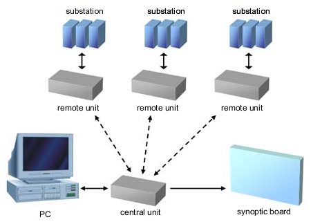
Central unit
Central unit maintains the link with remote units via radio link or signal lines (phone line). The link is bi-directional, enabling control and monitoring of remote equipment. All changes registered in the system are reported by the remote units to the central unit, which then forwards them to the computer.
In addition, central unit can be connected to the synoptic board, to show important data to a number of operators. The remote unit also has the ability to be connected to a local computer, to obtain data in case the link from the remote to the central unit fails.
Central unit provides 2048 output signals, to be connected to the synoptic board (each signal corresponds to one element of the network).
Remote unit
Centralised remote unit
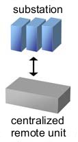 A centralised remote unit is installed if the substation already has signal conditioning and all individual analogue signals are brought to one point.
The remote unit is located in a 19" RACK metal cabinet. The basic configuration of a remote unit consists of a supply, computer and communications board. Additional boards can be added if required.
The capacity of individual boards in a remote unit is as following:
- Inputs board - 64 digital (on / off) signals.
- Command board - 32 outputs, grouped in 16 pairs (on/off switching).
- Measurement board - 16 analogue inputs.
- Counter board - 8 inputs for signals from pulse counters.
The total capacity of the centralised remote station is:
- 2048 digital signals,
- 256 analogue signals (current, voltage, power),
- 256 commands,
- 256 signals from pulse counters.
Supply 220V AC or using source of 110V DC from the station.
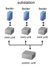
Distributed remote unit
 A distributed remote unit requires less intervention in the substation itself allied with far less work and materials (wire) required for signal wiring, compared to the centralised method of signal conditioning.
In addition, this concept ensures that signals are detected at the origin, without unnecessary intermediaries, such as long wires and relays, reducing reliability.
A distributed remote unit requires less intervention in the substation itself allied with far less work and materials (wire) required for signal wiring, compared to the centralised method of signal conditioning.
In addition, this concept ensures that signals are detected at the origin, without unnecessary intermediaries, such as long wires and relays, reducing reliability.
This remote unit consists of a central communication unit and mini units located in feeder cells. Each mini unit corresponds to one cell (feeder cell 35kV, transformer cell 35KV, transformer cell 10kV, measurement and busbar connection cell, feeder cell 10kV, station’s own consumption).
Supply 220V AC or using source of 110V DC from the station.
The capacity of one mini unit is:
- 8 to 32 digital signals
- 2 to 16 analogue signals (current, voltage, power)
- 2 to 8 commands (switch, transformer regulation, etc.)
- 2 to 8 signals from pulse counters.
Remote unit – data concentrator
This type of remote unit is used for control of the substations that have built in microprocessor protection of various manufacturers. Measured signal values from the protection are sent to the remote unit – communications module, which then forwards them to the centre.
Communication with the microprocessor protection is established via appropriate connectors for SCADA communication. We support the following communication protocols: MODBUS and IEC 60870-5-103.
RC1 SCADA
This software package enables integration of all system capabilities and centralisation of the data being collected by the system, as well as centralised network control. The program enables recording of network status, in parallel with the synoptic board at several levels, starting to the highest voltages down to a single pole diagram of individual stations and the 10kV network. It is possible to monitor and control several remote network parts simultaneously.
RCI SCADA records all alarms from the remote stations and automatically changes the state of the network with a sound signal. Changes of state and alarms are registered permanently in the computer and by printing data about elements with changed state. All events in the system are stored as a standard data log, which can be later viewed and printed.
Measurement data that arrive from the remote stations are permanently archived and can be processed later. Current measured values are shown along with the cells from which they originate. Measured data for any day (for a particular part of the system) can be shown as a diagram, and printed as a chart or a spreadsheet.
 Return to the top of the page
Implementation
It is important to emphasize that the implementation of RC1 system can be done in steps, depending on customer preferences and circumstances. This means that the program can be implemented separately from the hardware, if the user just wants to process and store data on the computer. At the same time this can be the first step in full system implementation.
System RC1 with all its functions can be implemented to a part of a network, and then later the remainder of the network can be included. System also offers the facility of expansion in case of new stations being added to the network or even large parts of the network being added.
Furthermore, at the customer’s request, it is possible to implement additional functions, both in terms of hardware and software.
If a customer does not have in house expertise for design and modification of the substations (for a system of distribution control), we can offer a complete solution, including assessing the current state of the substations, project design and appropriate upgrade.
Return to the top of the page